Chapter 5 Laying of Cables
Section 1 General Provisions
Article 5.1.1 Before the laying of cables, the following requirements shall be checked:
First, the cable channel is open and the drainage is good. The metal part of the anti-corrosion layer is complete. The lighting and ventilation in the tunnel meet the requirements.
Second, the cable model, voltage, specifications should meet the design.
Third, the appearance of the cable should be free from damage and good insulation. When there is any doubt about the sealing of the cable, wet judgment should be made; the buried cable and the underwater cable should pass the test.
Fourth, the oil pressure of the oil-filled cable should not be lower than 0.15MPa; the fuel supply valve should be in the open position, and the action should be flexible; the pressure gauge should indicate no abnormality; all the pipe joints should have no leakage oil; the oil sample should pass the test.
Fifth, the cable payoff frame should be placed securely, and the strength and length of the steel shaft should be matched with the weight and width of the cable tray.
6. Calculate the length of each cable according to the design and actual path before laying, reasonably arrange each cable and reduce the cable connector.
VII. There should be reliable safety measures when laying cables in charged areas.
Article 5.1.2 When laying cables, the waterproof layer of cable trenches, tunnels, cable wells and manholes shall not be damaged.
In Article 5.1.3, a four-wire power cable shall be used in a three-phase four-wire system. Instead of a three-core cable, a single-core cable, or a wire and cable metal jacket shall be used as the neutral conductor.
Article 5.1.4 The power cable used in parallel should have the same length, type and specification.
Article 5.1.5 of the power cable should have spare length in the vicinity of the terminal head and the connector.
The distance between each supporting point of the cable of Article 5.1.6 shall meet the design requirements. When the design is not specified, it should not be greater than the values listed in Table 5.1.6.
Table 5.1.6 Distance between each supporting point of the cable (mm)
> Cable Type > Laying Mode
> Horizontal >Vertical
> Power Cables Full Plastic >400 >1000
Medium and low voltage cables other than all-plastic type >800 >1500
Class="MsoNormal">High-voltage cable of 35kV and above >1500 >2000>Control cable >800 >1000
Note: When the full-plastic power cable is laid horizontally along the bracket to fix the cable, the distance between the support points is allowed to be 800mm.
The minimum bending radius of the cable of Article 5.1.7 shall comply with the provisions of Table 5.1.7.
Article 5.1.8 The maximum difference between the highest point and the lowest point of the viscous oil-impregnated paper-insulated cable shall not exceed the requirements of Table 5.1.8. When the requirements cannot be met, cables suitable for high level difference shall be used.
Table 5.1.7 Minimum bending radius of cables
> Cable Type >Multicore >Single Core
> Control Cables >10D
Rubber Insulated Power Cable Lead-free, Steel Jacket >10D
Bare lead sheath >15D
Steel sheath >20D
PVC insulated power cable >10D
Crosslinked polyethylene insulated power cable >15D >20D
Oil-impregnated Paper Insulated Power Cable >Lead Bag >30D
> Lead package Armored >15D >20D
No outfit >20D
> Self-contained oil-filled (lead package) cable >20D
Note: D in the table is the outer diameter of the cable.
Table 5.1.8 Maximum permissible layups for viscous oil-impregnated insulation lead-insulated power cables
Voltage (kV) Cable sheath structure Maximum allowable dislocation (m)
1 No outfit 20
Armored 25
6 to 10 Armored or unarmored equipment 15
35 Armored or unarmored 5
Article 5.1.9 When laying the cable, the cable shall be led from the upper end of the plate. The cable shall not be allowed to drag on the bracket and the ground. The cables must not be mechanically damaged, such as armored flattening, cable twisting, or splitting of the sheath.
Article 5.1.10 The maximum traction strength when mechanically laying cables shall comply with the requirements of Table 5.1.10. The total pulling force of oil-filled cables shall not exceed 27 kN.
Table 5.1.10 Maximum cable pull strength (N/mm2)
Traction method Traction head Wire mesh cover
Stressed parts Copper core Aluminum core Lead sleeve Aluminum sheath Plastic sheath
Allowed traction strength 70 40 10 40 7
The speed of 5.1.11 mechanical cabling shall not exceed 15m/min. When laying cables of 110kV and above or laying on more complex paths, the speed shall be appropriately slowed down.
Article 5.1.12 When laying large cross-section cables under the complex conditions, the organization of the construction shall be carried out to determine the laying method, the laying position of the reel, the direction of the cable pulling, the checking of the traction force and the side pressure, and the laying of the personnel and equipment.
Article 5.1.13 When laying cables mechanically, anti-smashing devices shall be installed between the traction head or wire mesh sleeve and the traction steel cable.
When 5.1.14 110kV and above cables are laid, the lateral pressure at the turning point shall not exceed 3kN/m.
Article 5.1.15 After the oil-impregnated paper-insulated power cable is cut off, the end shall be immediately sealed; the plastic insulated cable shall have a reliable moisture-proof seal; the oil-filled cable shall meet the following requirements after being cut:
1. In any case, pressure tanks should be used to maintain oil pressure in any section of the oil-filled cable.
Second, when connecting the oil pipeline, the air in the tube should be eliminated and fuel injection should be used.
Third, the cut-off point of the oil-filled cable must be higher than the cables on both sides.
Fourth, cut off the cable should not have metal chips and dirt into the cable.
Article 5.1.16 When laying cables, the cable shall be allowed to lay the minimum temperature. The average temperature within 24 hours before laying and the temperature at the laying site shall not be lower than the requirements in Table 5.1.16; when the temperature is lower than the values specified in Table 5.1.16 , should take measures.
Table 5.1.16 Allows the lowest temperature for the cable to be laid
> Cable Types >Cable Construction >Allows the lowest temperature (°C)
> Oil-impregnated paper-insulated power cable Oil-filled cable >-10
Other oil-paper cables >0
> Rubber insulated power cable Eraser or PVC sheath >-15
Bare lead set >-20
Lead sheathed steel tape armor >-7
> Plastic Insulated Power Cables >0
> Control Cables Cold Resistant Jacket >-20
Rubber insulated PVC sheath >-15
PVC insulated PVC sheath >-10
Article 5.1.17 layout of power cable connectors shall meet the following requirements:
First, the laying of the cables, the joints should be staggered with each other.
Second, the cable when the application of the joint, the use of brackets fixed.
Third, outside the cable junction box should be outside to prevent mechanical damage protection box (except for epoxy joint box). The protective box inside the frozen soil layer should be filled with asphalt.
Article 5.1.18 should be arranged neatly when laying cables, and should not be crossed, fixed, and set up signs for fashion.
The installation of the 5.1.19 sign shall meet the following requirements:
1. In cable terminations, cable joints, bends, mezzanines, both ends of tunnels and shafts, in manholes, etc., signage shall be installed on the cables.
Second, the line number should be marked on the signboard. When there is no number, the cable type, specification and starting and ending point shall be stated; the parallel used cable shall have the sequence number. Signs should be clear and easy to fall off.
Third, the logo should be unified. Signs should be able to prevent corrosion and should be securely mounted.
Article 5.1.20 fixing of cables shall meet the following requirements:
First, the cable should be fixed in the following places:
1. The cable laid vertically or inclined at more than 45° is laid on each bracket; every 2m on the bridge;
2. Cables laid horizontally should be at both ends of the cable and at both ends of turn and cable joints; when there is a requirement for cable spacing, every 5 to 10m;
3. The fixation of single-core cables should meet the design requirements.
2. The single-core cable of the AC system or the fixed fixture of the phase-separated lead sleeve cable after the phase separation shall not constitute a closed magnetic circuit.
Third, bare lead (aluminum) sets of cable fixed place, should be added soft liner protection.
Fourth, the sheath insulation requirements of the cable, insulation should be added in the fixed pad.
Article 5.1.21 The metal sheath or cable metal pipe of the Mingfa cable along the bridge that is passed through the electrified railway or the electrified railway shall be insulated along its full length from the metal components of the metal bracket or bridge.
When the cable enters the cable channel, tunnel, shaft, building, plate (cabinet) and penetrating the pipe, the inlet and outlet shall be closed and the nozzle shall be sealed.
Article 5.1.23 lighting beacons equipped with lightning rods, cable laying fashion should comply with the relevant requirements of the current national standard "Electrical Installation Engineering Grounding Device Construction and Acceptance Specifications".
Section 2 Laying of Cables in Production Plants and Tunnels and Channels
The arrangement of cables in Article 5.2.1 shall meet the following requirements:
First, the power cable and the control cable should not be placed on the same shelf.
Second, high and low voltage power cables, strong and weak control cables should be arranged in layers in order, and generally should be configured from top to bottom; but when high voltage cables with more than 35kV are introduced into the panel, they can meet the requirements of bending radius. On the configuration.
Article 5.2.2 The laying of the power cables, the net distance between them should meet the design requirements.
Article 5.2.3 The laying of the cable on the bracket shall meet the following requirements:
First, the control cable on the ordinary bracket, should not exceed 1 layer; bridge should not exceed 3 layers.
Second, the exchange of three-core power cable, in the ordinary support hanger should not exceed 1 layer; bridge should not exceed 2 layers.
Third, AC single-core power cables should be placed on the same side of the bracket. When arranged in close contact with the right triangle, they should be fastened with straps every 1m.
Article 5.2.4 The net distance between cables and heat pipes and thermal equipment shall be not less than 1m in parallel and shall not be less than 0.5m when crossing. When the conditions are limited, heat insulation protection measures shall be taken. The cable channel shall avoid the fire hole of the boiler and the explosion-proof door of the pulverizing system; when the conditions are restricted, heat insulation and fire prevention measures such as pipe penetration or closed tank box shall be adopted. Cables should not be laid parallel to the upper part of thermal equipment and heat pipes.
Article 5.2.5 The cables that are applied in the interior and in the cable trenches, tunnels, and shafts with a protective layer shall be stripped of the protective layer and be preserved.
Article 5.2.6 After the cable is laid, it is necessary to remove the debris in time and cover the cover. If necessary, seal the cover gap.
Section 3 Laying of Cables in Pipes
Article 5.3.1 In the following locations, the cable shall have a protective tube with a certain mechanical strength or be equipped with a protective cover.
First, cables enter buildings, tunnels, floors and walls.
Second, from the channel leading to the pole, equipment, wall surface or inside the house where the pedestrians are easily accessible, from the height of 2m below the ground section.
Third, other places that may be mechanically damaged.
The depth of the protective tube buried in the non-concrete floor should not be less than 100mm; the length of the diffuser protruding from the building should not be less than 250mm, and the root of the protective cover should not rise above the ground.
Article 5.3.2 There should be no accumulation of water inside the pipeline, and no debris plug. When wearing the cable, do not damage the sheath. Use a non-corrosive lubricant (powder).
Section 5.3.3 Cable Casings Before laying cables, clear them and remove them.
Article 5.3.4 The number of cables passing through the pipe shall meet the design requirements; the AC single-core cable shall not be penetrated into the steel pipe alone.
Section IV Laying of Directly Buried Cables
Article 5.4.1 Protective measures shall be taken in the section of the cable route that may cause the cable to suffer mechanical damage, chemical action, underground current, vibration, thermal influence, rot quality, pests, and other hazards.
The buried depth of cable in Article 5.4.2 shall meet the following requirements:
First, the cable surface distance from the ground should not be less than 0.7m. When crossing the farmland, it should not be less than 1m. In the introduction of buildings, crossing with underground buildings and bypassing underground buildings, shallow burial, but protective measures should be taken.
Second, cables should be buried below the frozen soil layer. When conditions are limited, measures should be taken to prevent damage to the cables.
Article 5.4.3 The minimum distance between the cables and the parallel and crossing between cables, roads, buildings, etc., shall comply with the requirements of Table 5.4.3. It is forbidden to lay the cable parallel to the pipe above or below it. Special circumstances shall be implemented as follows:
Table 5.4.3 Minimum net distance between cables, between cables and pipes, roads, and buildings, parallel and cross
Projects Parallel Cross
Power cable room and its control cable 10kV and below 0.10 0.50
10kV or more 0.25 0.50
Control cable room - 0.50
Cable between different use departments 0.50 0.50
Heat Pipes (Gutters) and Thermal Equipment 2.00 0.50
Oil pipeline (pipe channel) 1.00 0.50
Combustible gas and flammable liquid pipes (ditch) 1.00 0.50
Other pipes (pipes) 0.50 0.50
Railroad tracks 3.00 1.00
Electrified railway tracks AC 3.00 1.00
DC 10.0 1.00
Highway 1.50 1.00
Urban street pavement 1.00 0.70
Rod Foundation (Edge) 1.00 —
Building Foundation (Edge) 0.60 -
Drain 1.00 0.50
Note: 1 The net distance between the cable and the road can be reduced when the situation is special.
2 When the cable is piped or other pipes have protective facilities such as insulation, the net distance in the table shall be calculated from the wall of the pipe or the outer wall of the protection facility.
1. Between the power cable room and the cable between the control cable or the different use departments, the parallel distance can be reduced to 0.1m when the cable is passed through the pipe or separated by a partition.
2. Between the power cable room, the control cable room, and between them, the cables of different use departments are within 1m in front of and behind the intersection. When the cables are passed through the pipes or separated by partitions, the cross distance can be reduced to 0.25. m.
3. Between the cable and the hot pipe (ditch), oil pipe (ditch), combustible gas and flammable liquid pipe (ditch), thermal equipment or other pipe (ditch), although the net distance can meet the requirements, but the inspection pipeline may be When the cable is damaged, protective measures shall be taken within 1m before and after the intersection; when the cross-net distance cannot meet the requirements, the cable shall be inserted into the pipe, and the net distance may be reduced to 0.25m.
(4) When the cables and heat pipes (ditches) and thermal equipment are parallel and intersecting, heat insulation measures shall be taken so that the temperature rise of the soil around the cables does not exceed 10°C.
5. When DC cables are parallel to the rails of electrified railways and their net distance cannot meet the requirements, galvanic corrosion prevention measures should be taken.
Article 5.4.4 When cables cross railways, roads, city streets, and factory roads, they shall be laid in strong protective pipes or tunnels. The two ends of the cable duct should extend 2m from each side of the road embankment; extend the drain 0.5m; extend the pavement in the city streets.
Article 5.4.5 The upper and lower parts of the buried cable shall be covered with a layer of soft soil or sand not less than 100mm thick, and shall be covered with a protective plate covering a width exceeding 50mm on each side of the cable. The protective plate may be a concrete cover plate. Or bricks.
There should be no stones or other hard debris in soft soil or sand.
Article 5.4.6 Directly buried cables shall be provided with obvious azimuth signs or stakes every 50 to 100m in the straight section, at the joints of cables, at turns, at buildings, etc.
Article 5.4.7 Before the cable is directly buried in the soil, it shall be accepted by the concealed project. The backfill soil should be layered and compacted.
Section 5 laying of underwater cables
Section 5.5.1 underwater cables shall be whole. When the entire cable exceeds the manufacturing capacity of the manufacturer, soft connectors can be used.
Article 5.5.2 The cables passing through the river should be laid in places where the river bed is stable and where the bank is less damaged. When laying cables at docks, anchorages, harbours, ferries and berths, reliable protective measures must be taken. When conditions permit, it should be buried deeply.
Article 5.5.3 The laying of underwater cables must be laid flat on the bottom and not allowed to float. When conditions permit, it should be buried in the river bed (under the sea) less than 0.5m.
Article 5.5.4 The spacing of underwater cables laid in parallel shall not be less than 2 times the water depth of the highest water level. When buried below the river bed (submarine), the spacing shall be determined according to the laying method or the working ability of the burying machine.
Section 5.5.5 of the underwater cable leading to the shore shall be protected by pipe or protective cover. The scope of protection shall be such that the lower end is where the vessel is stranded and the poles cannot reach the lowest water level; the upper end is higher than the maximum flood. Bit. At the lower end of the protection range, the cable should be fixed.
Article 5.5.6 When a cable route crosses a stream or stream, it should be piped or buried deep enough under the riverbed.
Article 5.5.7 The joints connecting the shore water bottom cable and the land cable shall be equipped with anchoring devices.
Article 5.5.8 The method of laying underwater cables, the choice of laying vessels and the design of the construction organization shall be determined according to such factors as the laying length, outer diameter, weight, water depth, flow velocity, and the topography of the riverbed.
Article 5.5.9 When laying the underwater cable, when the cable is installed on the entire cable, according to the water conditions, the cable plate can be placed on the shore or on the ship. When laying, the pontoon float can be used. It is forbidden to pull the cable under the water.
When the 5.5.10 underwater cable cannot be installed, it shall be handled in bulk. The laying procedure should be preceded by a cable coil around the laying ship's warehouse, and then through the top of the warehouse overhead, pulleys, brakes into the sink into the water, tied with a tug, self-capping or laying with a wire rope.
Article 5.5.11 The choice of laying ships shall meet the following conditions:
1. The capacity, deck area and stability of the ship's warehouse should meet the requirements for cable length, weight, bending radius and workplace.
Second, the laying ship should be equipped with brake devices, tension measurement, length measurement, water angle, depth and navigation, positioning and other equipment, and equipped with communications equipment.
Article 5.5.12 The laying of submarine cables shall be carried out during low tidal, turbulent or dry periods, with clear sightlines and winds of less than five levels.
The lay-offs on the laying ship 5.5.13 shall maintain an appropriate back-twist height. Lay the tension according to the depth control of the water when laying, and make the water inlet angle 30°~60°; when using traction pushing, the speed should be 20~30m/min; when using a tug or self-propelled traction, the speed Should be 90 ~ 150m/min.
Article 5.5.14 When laying underwater cables, cross-straits shall be guided by design. When laying, position measurement should be performed to correct the route and check the length of laying.
Article 5.5.15 When the underwater cable is led to the shore, all the remaining lines shall be floated on the surface of the water and then towed on land. The cables floating on the water should sink into the bottom according to the design path.
Article 5.5.16 After the laying of underwater cables, diving inspections shall be made. The cables shall be laid flat. The cables on the riverbed shall not be left unconnected. And measure the exact location of the cable. In both sides must be set according to design signs.
Henan Sanheng Industrial Co., Ltd. , founded in 2000, It is one of the top wire and cable manufacturers in China's wire and cable industry for nearly 20 years. the company has more than 5 production lines.
The production cable can be divided into more than 50 varieties and subdivided into 1000 specifications.All products have passed national certification, such as China compulsory certification, bv certification, Nigerian SONCAP certificate, China national industrial certification, etc. China national industrial production license, etc.It also has the ability to produce products that meet international standards, such as iec, ce, rohs, etc.
If you want to buy wires and cables, you can ask the customer service staff and we will get back to you as soon as possible.
-
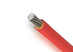
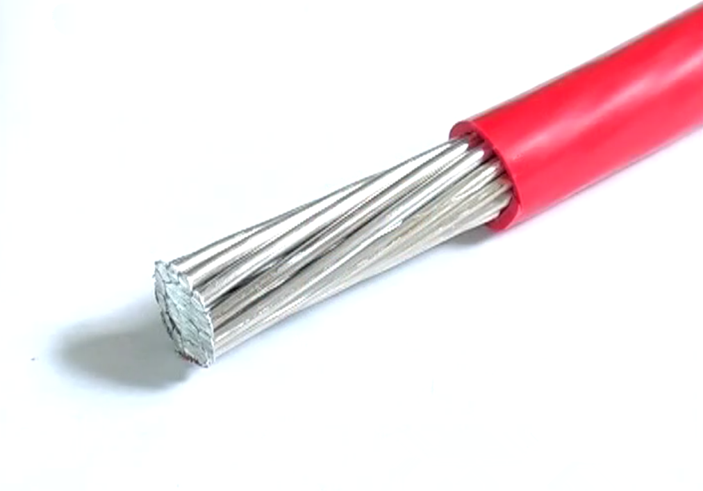
PVC Insulated Aluminum Cable
Conductor:Aluminum Conductor of Class 1/2 (Solid)
Insulation:PVC Compound
Insulation Color:Red, Blue, Green, Yellow, Brown, Black, Grey, White, Pink, Orange, Yellow/Green
-
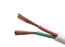
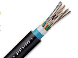
Flexible Flat Cable
Conductor:Stranded Copper Conductor of Class 5/6 (Flexible)
Insulation:PVC Compound
Insulation Color:Red, Blue, Yellow/Green or as request
-
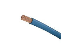
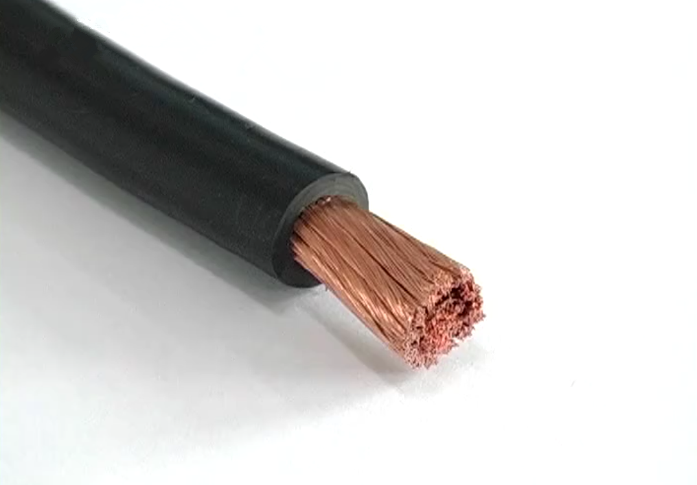
Single Core Flexible Cable
Conductor:Stranded Copper Conductor of Class 5 (Flexible)
Insulation:PVC Compound
Conductor Color:Red, Blue, Green, Yellow, Brown, Black, Grey, White, Pink, Orange, Yellow/Green
-
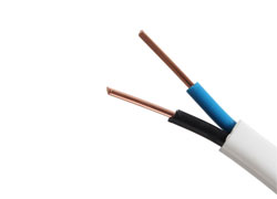
Twin and Earth Cable
Conductor:Class 1/2 copper conductor (solid)
Insulation:PVC Compound
Insulation Color:Red, Blue, Yellow/Green or as request